- 您现在的位置:买卖IC网 > Sheet目录1219 > HIP9011EVAL1Z (Intersil)BOARD EVALUATION FOR HIP9011
�� �
�
�Application� Note� 9770�
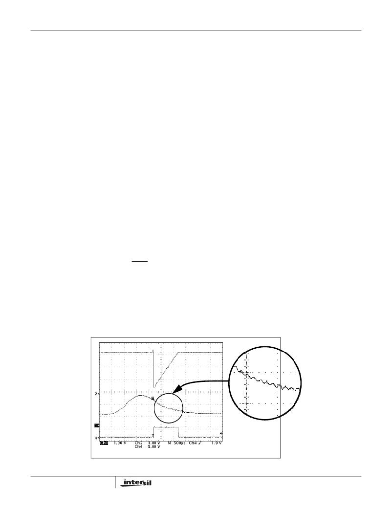
�display� is� the� 200kHz� clock� signal� that� only� appears� during� the�
�integration� portion� of� the� sample� cycle.� This� signal� causes�
�aliasing� or� a� “low� frequency� beat”� in� the� oscilloscope� display�
�between� the� 500� samples� and� the� 200kHz� pulses� appearing� on�
�the� ramp� only� during� the� integration� interval.� Once� the� signal� is�
�acquired,� the� INTOUT� signal� during� the� hold� period� remains�
�constant� and� free� of� the� 200kHz� pulses� until� the� next� integration�
�period.� The� sample� and� hold� circuit� within� the� HIP9011� is� timed�
�so� that� it� only� samples� during� a� non� pulse� period,� thus�
�preventing� it� from� acquiring� either� peaks� or� valleys.�
�The� lower� trace� of� Figure� 5� more� accurately� depicts� the�
�INTOUT� waveform.� Note� the� 200kHz� clock� signal� on� the�
�integrator� ramp.� One� million� samples� were� used� for� this�
�display.� Also� note� that� INTOUT� is� constant� between�
�integration� cycles� and� shows� no� 200kHz� pulses.�
�For� observation� purposes� only,� or� when� working� with� a�
�digital� oscilloscope� with� limited� samples,� an� external� anti�
�aliasing� filter� may� be� assembled� with� a� series� 51k� resistor�
�and� a� 510pF� capacitor� to� ground.� The� filter� attenuates� the�
�internal� 200kHz� clock� signal� during� integration,� For�
�operation� with� a� sampling� A/D� converter� that� is� strobed� and�
�samples� after� the� integration� cycle,� no� filter� is� needed.�
�Laboratory� Setup�
�It� is� desirable� to� get� a� “feeling”� for� the� operation� of� the�
�HIP9011� before� proceeding� to� an� evaluation� with� an� engine,�
�Figure� 6� shows� a� bench� test� setup� where� this� can� be� easily�
�accomplished.�
�One� generator� is� used� to� provide� the� INT/HOLD� signal� to� the�
�Evaluation� Board.� In� the� actual� application� this� signal� would� be�
�supplied� by� the� engine� controller.� The� width� of� this� signal� may�
�vary� from� several� hundred� microseconds� to� several�
�milliseconds� depending� upon� the� engine� rpm� and� engine� type.�
�Generally,� there� is� a� large� signal� at� high� engine� rpms� and� lower�
�signals� at� low� rpms.� At� the� lower� rpm,� the� integration� period�
�may� be� extended� to� gain� more� samples� and� effectively� produce�
�high� sensitivity� to� obtain� more� output.�
�The� second� generator� provides� the� signal� that� serves� as� a�
�knock� signal.� It� is� interesting� to� note� the� variation� of� the�
�integrator� output,� INTOUT,� as� the� IC� filter� frequency� or� oscillator�
�frequency� is� varied� from� 200Hz� to� 100kHz.� Figure� 4� shows� the�
�IC’s� filter� response� as� a� sweep� frequency� signal� is� applied� to�
�only� the� filter� circuit� for� five� selected� filter� frequencies� from�
�1.22kHz� to� 19.98kHz.� These� curves� were� taken� only� of� the�
�filters� to� show� their� response� and� comparatively� constant�
�output� through� out� the� entire� filter� frequency� range.�
�Figure� 7� shows� the� HIP9011� connected� to� an� engine.� The�
�microcontroller� with� inputs� from� the� engine,� provides� the�
�INT/HOLD� signal� to� initiate� operation� of� the� integrator� within�
�the� knock� signal� processing� IC.�
�Evaluation� Board�
�Figure� 8� shows� the� schematic� diagram� of� the� evaluation� board.�
�A� 4MHz� crystal� is� supplied� with� the� board.� 4MHz� ceramic�
�resonators� such� as� the� TDK� FRC4.0MCS� have� been�
�successfully� used� in� the� board.� Three� pins� are� provided� on� the�
�board� to� accept� resonators� to� replace� the� crystal.�
�A� prewired� input� amplifier� configuration� board� is� provided� as�
�shown� in� Figure� 9.� This� board� is� connected� for� single� ended�
�operation.�
�Figure� 10� shows� the� schematic� diagram� for� a� differential�
�input� board� that� may� be� wired� for� the� HIP9011.� This� may� be�
�fabricated� with� the� one� generic� blank� board� supplied� with� the�
�evaluation� board.�
�Figure� 11� is� a� top� view� of� the� evaluation� board.�
�Software� Displays�
�Figure� 12� shows� the� display� for� the� HIP9011� appearing� on� the�
�computer� when� using� the� Evaluation� Board� in� a� Microsoft?�
�Windows� ?� setup.� In� some� Windows� setups� the� text� displayed�
�may� override� the� boxes� and� be� difficult� to� read� due� to� computer�
�settings.� This� can� be� corrected� by� changing� the� font� size� on� the�
�computer.� This� is� described� in� the� “Installing� Knock� Signal�
�Processor� Software”� section� of� this� application� note.�
�FIGURE� 3.� WAVEFORMS� ASSOCIATED� WITH� THE� HIP9011�
�3�
�AN9770.1�
�November� 6,� 2006�
�发布紧急采购,3分钟左右您将得到回复。
相关PDF资料
HM2H08P115LF
HM2H08P115LF SHROUD STYLE B LF
HM2P12P1LF
HM2 M INS STYLE N WIDE
HM2R06P1LF
MILLIPACS RCP HSG
HM2SC22A8
HM2SC22A8-MILLIPACS 2R SHIELDING
HM2SC22B
HM2SC22B-MPACS SHIELD COVERS
HMC6352-DEMO
DEMONSTRATION BOARD FOR HMC6352
HMEG
FUSEHOLDER W/COVER FOR AMG FUSE
HMUA-F3-A126
CONN FERRULE MU .126MM DIA
相关代理商/技术参数
HIP9020
制造商:INTERSIL 制造商全称:Intersil Corporation 功能描述:Programmable Quad Buffer with Pre and Post Scaler Dividers
HIP9020AB
制造商:Rochester Electronics LLC 功能描述:- Bulk
HIP9020ABR3327
制造商:Rochester Electronics LLC 功能描述:- Bulk
HIP9020ABR3327S
制造商:Rochester Electronics LLC 功能描述:- Bulk
HIP9020AP
制造商:Rochester Electronics LLC 功能描述:- Bulk
HIP9021
制造商:INTERSIL 制造商全称:Intersil Corporation 功能描述:Portable Battery Drive/Torque Controller for N-Channel MOSFETs in Motor Control Systems
HIP9021IB
制造商:INTERSIL 制造商全称:Intersil Corporation 功能描述:Portable Battery Drive/Torque Controller for N-Channel MOSFETs in Motor Control Systems
HIP9022
制造商:INTERSIL 制造商全称:Intersil Corporation 功能描述:Dual High Speed Laser Driver